Micro Welding Science
By: Dr. Aaron Astle – PHD
Introduction
Many individuals may not understand the elemental differences of various welding/micro-joining technologies that exist in the market including the strengths and weaknesses of each technology as they interact with a variety of metals. The purpose of this paper is to discuss in detail four major welding technologies (laser, pulse-arc, resistance, solder) and how they join various metals at a fundamental level. By better understanding, these welding principles and how metal specific weld properties are generated, organizations and individuals in the jewelry industry will be better prepared to make the best decision for their micro-joining needs. They may discover that having more than one technology is best.
Solder Joining
Soldering is a joining process that has been around for thousands of years. [36] It is a technology that is both simple and surprisingly complex. Once everything has been set up and prepared correctly, soldering is a simple, repeatable and reliable process. However, it is complex in that surface condition, metal flow characteristics, oxide, surface contaminants, and heat application can all change the results dramatically. Discussions of how to solder and some of the proper preparations for soldering can be found in an excellent Santa Fe Symposium article by Jeanette Caines as well as other online resources. [35],[38] This section will only discuss solder joining briefly, focusing on topics that allow insight into when the solder is a preferable joining method compare to other available welding technologies.
The term soldering used in the jewelry community is typically called brazing in other industries. However, the distinction between soldering and brazing is simply an arbitrary choice of melting temperatures for the solder or braze material. According to the American Welding Society (AWS), braze materials are those that melt above 450 C°. Brazing is where the braze material is liquid below the melting temperature of the metal to be joined. Soldering has a similar definition but with the melting temperature of the solder material below 450 C°. [39] For the purposes of this discussion, we will refer to the brazing process as soldering.

Figure 1. Solder joint strength depends on joint gap distance. The graph shows normalized joint strength vs joint gap distance. [40]
Solder joint strength is strongly dependent on part fit. When the solder is in its liquid phase, capillary action, due to liquid surface tension, acts to draw the metal through the gap. For a given combination of solder and metal, there is an optimum gap spacing to provide the best capillary action and maximum joint strength. Figure 1 shows a typical strength vs. joint gap curve. This curve has been normalized to illustrate general trends. The curve shows that a press fit (no space) has reduced joint strength because no solder material was drawn into the space between the parts by capillary action. At a spacing of 0.0015 inches, for this example curve, the best capillary action occurs to fill the joint and produce the best mechanical properties of the material (no voids, etc.). As the gap distance increases, strength continues to decrease due to insufficient capillary force to fill the gap completely, creating voids, etc. For jewelry, the term typically used to describe a good joint preparation is “light tight.” This description provides for a gap spacing near the optimum 0.0015 inches shown in the graph. For dissimilar metals, thermal expansion properties at the soldering temperature of the parts should be considered to ensure optimum joint gap distance.
Other important considerations such as surface cleanliness, the application of flux, fixturing parts, etc. are all critical to producing strong and consistent joints. Contaminates, such as finger oils, can create oxides and other deposits during the heating process that prevent solder wetting and flow. Proper cleaning prior to joining will prevent void formation from a poor flow and ensure proper full joint wetting. As a general rule, flux is required during the soldering process; exceptions include soldering in inert atmospheres and solders that contain some sort of flux agent. The flux acts to remove oxides and promote metal wetting at soldering temperatures. Part fixturing is important to prevent part misalignment during the heating process. Gravity, increased mobility of the parts as the solder melts, and pushing from the flame all act to misalign the parts during the soldering process. One simple way of fixturing is to use an alternate welding technology (e.g. resistance welding, laser welding, pulse arc welding) to make small positional joints before the soldering process. These small joints can be placed in locations that will not be noticed or can be made small enough that they will be hidden by the solder itself. Resistance welding can also be used for placing solder chips at the correct location for proper capillary action. As has been discussed in other articles and tutorials, the proper placement of the heat source also plays a large role in drawing the solder into the joint. Typically, heat is applied to the back of the joint in such a way as to reduce flow front freezing and decrease fluid viscosity as the molten solder is wicked into the joint. Other heating technologies, in addition to a torch, to melt and join the workpiece also exist, such as brazing ovens and induction heating elements. These technologies offer some advantages in production rate and time but come at a substantially higher cost.
Resistance Welding
Resistance welding includes any process that uses that uses the electrical resistivity of the existing metal to heat and melt the metal using an electrical current. For industrial applications, this process is often called “spot” welding as the electrical current is usually applied via compression between two electrodes leaving a circular weld “spot” when the welding process has been completed. In the jewelry and metal-smithing community, resistance welding is often called “tack” welding. This term probably developed as jewelers used resistance welding technology to simply place pieces during their assembly but made the welds weak enough to not be permanent. Unfortunately, this also has led to the mistaken implication that resistance welding can only be used for weak connections. However, we will demonstrate that resistance welding can be used for high volume, permanent assembly under the right conditions.
There are two regimes of resistance welding. The first is large-scale welding as seen in the manufacturing of automotive bodies, etc. In this welding regime, the two materials to be joined are pinched between two large electrodes and put under tremendous pressures (10’s of thousands of PSI). The material’s internal resistance, often called “bulk” resistance, is then used to heat and create the weld spot. The second regime is small-scale or micro resistance welding. For this application, the two materials are again placed between two electrodes with much less pressure and much smaller electrodes. When small parts and light pressures are used, the welding heat is created by the contact resistance between the two materials and not by the materials bulk resistance. Micro resistance welding is more typical for jewelry applications.
The resistivity of a material can be described as fundamental to a specific metal. Resistivity describes how much a material opposes the flow of electrons. Equation 1 shows that, for a given resistivity, the more cross-sectional area that the electrical current passes through, there will be a lower electrical resistance.
Equation 1. 
Where R is the electrical resistance, ρ is the resistivity of the metal, L is the length of the material and A is the cross-sectional area of the electrical flow. In the case of a resistance (spot) weld, the area represents the space directly under the weld electrodes.
Another important relationship to understand in resistance welding is how weld current, contact resistance, and weld heat are associated. As shown in Equation 2, the weld heat (or power) Q is directly proportional to the square of the weld current I and to the 1st power of the contact resistance R.
Equation 2. 
Understanding contact resistance is the key to knowing how to successfully apply resistance welding techniques to welding jewelry. As depicted in Figure 2; when a metal is magnified to the micro-scale, the surfaces are neither flat nor smooth, but rather are made up of minuscule peaks and valleys. This means that the contact area between the two surfaces is not actually the area between them but a much smaller, more defined area where the peaks of these micro points meet. The reduced contact area due to these tiny peaks causes the electrical resistance between the parts to increase, proportionally to the reduced surface area, over the metals bulk resistance according to Equation 1. The small contact points have much higher resistance than the surrounding material and are the first to melt when electrical current is applied. The molten metal also has a higher resistance than the surrounding solid material and additional melting continues at the interface between the two parts.

Figure 2. On the microscale metal, surfaces are not flat but contain many small peaks and valleys.
Contact resistance can be adjusted by altering the number of microcontact points between the two materials. This can be accomplished by the application of pressure to force more of the micro points to touch. Figure 3 shows how micro point contacts can change with the application of pressure. From the figure, and by keeping Equation 1 in mind, we realize that the resistance of the interface is inversely related to the contact area between the two pieces. In simpler terms, the more pressure applied to the electrodes, the more contact between the two parts, and the lower the resistance that results between the parts. From Equation 2 we see that for a given weld current, more resistance equates to more heat generated. To summarize: High pressure = low weld heat, and low pressure = high weld heat. Even though Equation 2 indicates that weld current is much more important than contact resistance, a subtle change in weld pressure creates dramatic changes in the weld heat.

Figure 3. The number of contact points can change as more or less pressure is applied to force the two materials in together.
Table 1. The Electrical Resistivity of some Common Metals
| Material |
Resistivity
(Ohm m)*1×10^8 |
Yield Strength (MPa) |
| Silver | 1.59 | 124 |
| Aluminum | 2.65 | 145 |
| Gold | 2.24 | 120 |
| Copper | 1.724 | 70 |
| Brass – 63% Cu | 7.1 | 276 |
| Palladium | 10.5 | 205 |
| Platinum | 10.5 | 185 |
| Bronze | 13.4 | 137 |
| Stainless steel | 73 | 520 |
| Titanium T6 | 178 | 880 |
Using the properties outlined in Table 1 we can examine some different metals to understand their relative ease of resistance welding. From this chart, it is apparent that, relative to each other’s resistivity, silver would be exceptionally more difficult to resistance weld compared to stainless steel (46 times more resistive). Also listed in the chart is the approximate yield strength of these materials. For our present comparison of silver and stainless steel, think of the yield strength of a measure of how easily the micro peaks/contact points can be deformed by electrode pressure. Lower yield strength allows the metal to deform more easily under pressure, resulting in more micro peak/contact points and less overall resistance. Silver not only has a very low resistivity but also can be deformed with much less effort than the stainless steel as listed in the table. So even though the resistivity of silver compared to stainless steel would suggest for a given weld current that the generating weld heat would be 46 times greater for the stainless steel, it may even be higher than this if other factors like the materials softness and the effect of pressure are taken into account. All of these factors must be considered to optimize the best weld settings.
Table 2. Thermal Conductivity of Different Metals Highest to Lowest
| Material |
Thermal Conductivity
(W/m*K) |
Thermal Diffusivity α
(m^2/s) *1×10^6 |
Resistivity/Thermal Diffusivity * 1e4 |
| Silver, pure | 349.6 | 165.6 | 1.0 |
| Gold | 270.8 | 127 | 1.8 |
| Copper, pure | 331.8 | 111 | 1.6 |
| Aluminum, pure | 175.6 | 84.2 | 3.1 |
| Yellow Brass | 99.7 | 31 | 22.9 |
| Palladium | 71.8 | 24.6 | 42.7 |
| Platinum | 62.5 | 22.5 | 46.7 |
| Titanium | 17.9 | 7.3 | 2422.4 |
| Stainless Steel (304) | 38.7 | 4.2 | 1738.1 |
Thermal conductivity is another important material property that plays a crucial role in resistance welding, as well as solder joining, laser welding, and pulse arc welding. The thermal conductivity represents how quickly/easily thermal heat energy can be carried from a location of high temperature to one of lower temperature. In the case of resistance welding, the metal’s thermal conductivity acts to steal heat energy from the weld spot. This loss of this heat means that more energy must be added to metals with high thermal conductivity in order to produce the same spot size as a metal with lower thermal conductivity. The ratio of a metal’s thermal conductivity to its specific heat is also instructive. The specific heat of a material represents the amount of energy required to raise the temperature of a unit mass of the item one deg. centigrade. The ratio of thermal conductivity to specific heat can, therefore, be thought of as how fast it takes for the heat to make its way out of the weld spot and into the surrounding material. For example, if we look at the thermal diffusivity, with all things being equal, energy leaves silver approximately 39 times faster than stainless steel due to heat loss into the surrounding material and the energy required to raise the metals temperature enough for welding.
With the above discussion about the difficulty of generating heat from the intrinsic resistivity of some materials (e.g. silver), and also the difficulty of keeping heat at the weld site shown by the thermal diffusivity (e.g. silver), it is easy to understand how some materials will be more challenging than others to resistance weld. When evaluating the ease of resistance welding one material over another, the ratio of the resistivity (the ability to create weld heat) over the thermal diffusivity (how fast the heat leaves the weld site) is also instructive. Figure 4 shows a graph of this ratio as reported in Table 2. Please note that this ratio does not represent true ease of welding but rather the relative difficulty of welding one material over another. The graph indicates that silver and copper are the most difficult metals to resistance weld and that stainless steel and titanium are the simplest. In practice, some metals, such as aluminum and brass, have other problems that complicate their resistance welding process. However, in relation to jewelers, palladium, platinum, stainless steel, and titanium are all extremely simple to resistance weld. Gold, aluminum, and brass, on the other hand, can be resistance welded with the correct setup and power supply but are more easily “tack” welded before other forms of joining (solder, laser, pulse-arc). Finally, silver and copper are not only extremely problematic to resistance weld but are difficult to tack weld as well.
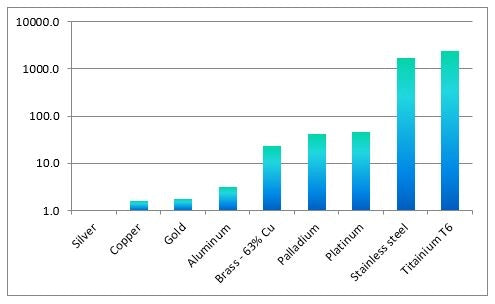
Figure 4. The Ratio of Electrical Resistivity over Thermal Diffusivity, (Heat Generated/Heat conducted away).
One way to overcome the difficulties presented by low resistance/high thermal conductivity metals is to change the welding heat generating strategy. For high resistance/lower thermal conductivity metals, copper welding electrodes are the typical electrode of choice. Using copper as the electrode can produce a low contact resistance which prevents heat generation at the welding tips; it can also carry away heat at the tip locations quickly before electrode damage occurs. Copper is also relatively inexpensive, which is an additional added benefit. However, from our discussion above we learn that welding materials such as copper and silver are challenging because very little resistive heat is produced, and the heat that is produced is conducted away quickly. The industry has solved this problem to some degree by generating the heat at the welding electrode instead of between the pieces to be welded. Typically tungsten or molybdenum electrodes are used for this purpose due to their high melting temperature and high resistivity. The electrode’s own contact and bulk resistance are used to generate the heat for the weld, this heat from the electrode tip must then melt the workpiece material inward until the two sides fuse. Some problems are typical in this electrode configuration. Because the melting takes place at the electrode tips and propagates inward toward the interface between the two materials, applied electrode pressure has a tendency to cause indentations at the weld location, and visible displacement of molten material can occur. Figure 5 shows a picture of a typical weld results in steel and copper for these configurations. This particular weld, copper electrodes were on the steel sheet and tungsten electrodes were on the copper sheet, is called a step weld. It required higher power than a steel to steel weld and indentations and visible at all weld locations.

Figure 5. Typical weld results for steel to steel and copper to copper spot welding.
Electrode marks can occur regardless of the material or geometry of the pieces if care is not taken in proper setup and settings. Below are some tricks that can be used to help avoid electrode marring:
- Shape the welding electrode to match the profile of the item to be welded. If the surface is domed, for example, use a concave welding electrode of the same radius.
- Use weldments to focus the weld energy and heat generation. Figure 6 shows a typical weldment used to focus weld heat. Weldments provide a focused starting location for weld current and melting to begin. Size the weldment so that when melted it will produce the desired weld volume. Weldments allow less energy to be used and also allow difficult-to-weld materials to be joined more easily as shown in Figure 7.

Figure 6. A Typical Weldment or projection Between Two Parts to focus the weld heat.

Figure 7. Difficult metals and combinations of metals can be joined by placing an easily welded material between them as the weldment using laser or pulse arc welding.
Some jewelry specific pulse arc welding machines have built-in resistance welders sometimes called Tack Welders. However, as with the welder shown in Figure 8, some of these welders are quite capable of creating a permanent resistance weld. By using 10 AWG cables (the largest cables this machine can use) many materials like platinum, palladium, titanium, stainless, and gold can be permanently bonded. Metals like silver and copper may only be tenuously tacked even at the maximum energy of the machine. In both cases, the amount of pressure the user applies is exceptionally important to the weld strength and repeatability. When tack welding jewelry; the user may hold the parts by hand, apply pressure, and then trigger the weld using a foot pedal. However, if using a resistance welder for higher volume manufacturing, it is highly recommended that the factory use some type of accurate fixturing and/or weld heads to provide consistent part placement and pressure. Figure 9 shows a Linear DC spot welder. This particular type of resistance welder can track the voltage, current, and power delivered to the workpiece, and can also adjust parameters to meet set point goals in real time. This feature allows for consistent welds to be produced despite small changes in material properties, tolerances, or operator error. In addition, these advanced resistance welders can keep track of data, such as total energy delivered, peak weld current, peak power, etc., during welding runs and apply statistical process control to help the operator keep the welding processes within predetermined parameters. One example of where this is useful is dealing with electrode maintenance. Over time the welding electrodes can deform under the repeated pressure, heat, and stress of the clamping and welding cycle. Statistical process control can detect these small incremental changes and stop the welding process to ensure electrode maintenance is performed before parts that fall out of tolerance and are rendered unusable.

Figure 8. The Orion 150S pulse arc and resistance welder.

Figure 9. The Sunstone LCD resistance welder with weld monitoring and control.
The jewelry industry uses a wide variety of metals. Some will resistance spot weld easily, while others can be very difficult to join using resistance welding technology. To best utilize this technology, look for simple geometries and ease of electrode placement. Determine if your metals have good physical properties that lend themselves to this form of joining, such as high resistivity, low thermal conductivity, etc. Then determine if welding aids like weldments are needed and can be easily applied to the welding process. Many welding companies will also offer free sample evaluations and consulting services. They also will typically return your samples and sign non-disclosure agreements so that there is no fear of losing unique designs, etc. Realize that when using such a service, the sample parts you send will most likely return cosmetically flawed and are only intended as a proof of concept. The more samples you provide the more likely the technician can optimize parameters such as pull strength or cosmetic appearance. During the welding technology selection process, consider various properties such as the required electrode material and the holding surface finish needed to prevent workpiece exterior damage, etc. Typically copper 182 (copper chromium) is used as a fixture material over brass due to its hardness compared to copper 110 and its high electrical and thermal conductivity. Sometimes replaceable locations under the weld spots are desirable to extend fixture life.
Laser Welding
There have been several excellent papers written for the Santa Fe Symposium that describe the basics of laser welding and various jewelry applications utilizing this technology. [26],[27],[28] For readers that are unfamiliar with laser welding, and that have not read these papers, I will cover some of the history and basics of laser light generation.
The theory that it might be possible to stimulate photon emission was first proposed by Albert Einstein in 1917. This revolutionary idea suggested that the creation of a coherent light beam was possible. The first working optical laser was produced nearly 43 years later in 1960 by Theodore Maiman at Hughes Research Laboratories using a synthetic ruby. The first Yttrium Aluminum Garnet (YAG) laser was developed 2 years later at Bell Labs. The YAG is the ancestor to the Nd. YAG that is typically used by jewelers today. One fun fact is that the first known use of the term LASER (Light Amplification by Stimulated Emission of Radiation) was coined by Gordon Gould in 1957, and was written in his notebook and notarized in a Bronx candy store. [29]

Figure 10. Basic components of an Nd. YAG laser system.
Fifty to sixty years of progress have taken today’s laser systems a long way. Figure 10 shows the basic elements of an Nd. YAG welding system. In its simplest form, the laser crystal is pumped full of potential energy using a high energy flash lamp. The crystal then releases this absorbed energy at a single wavelength (or very narrow band of wavelengths). The light is reflected between two mirrors, one mirror having a lower level of reflection that allows light to escape. The light is then focused and directed by the laser optics to the weld location. Some versions of this technology add potential energy to the YAG crystal with diode lasers or flash lamps and use a technology called a Q-switch to release all of the energy at one time. [29],[30] Figure 11 shows an example of a jewelers benchtop laser welder.

Figure 11. A bench top jewelers laser by Orion.
One fantastic property of lasers is the ability to direct energy to a location without the need for physical contact, as is a must for both resistance and pulse arc welding. However, this no contact advantage is tempered slightly by the requirement that the beam is focused and have a line of sight to the weld location. Small beam size is critical to producing the required energy per square mm necessary to melt metals. In a typical benchtop laser welder, the operator looks through a microscope, equipped with an optical shutter for eye protection, at a crosshair target over the workpiece. Usually, the laser focal point and the user microscope focal point have been aligned to the same plane. Positioning the workpiece under the microscope and bringing it into focus produces the correct beam diameter. The minimum beam diameter correlates to an exact match between the focal plane and the laser focus. By moving the focal point of the beam higher or lower, the welding machine changes the beam spot size. A typical minimum to maximum spot size will correspond to .2-2mm. Figure 12 shows a simple depiction of how the weld spot size is produced.

Figure 12. To adjust the weld spot diameter the user holds the workpiece at the optical microscope focal point and the laser welding machine changes the location of the beam focal point.
In most jewelry specific laser welders, the beam power, weld time, waveform shape, and weld diameter are controllable. The energy contained in the weld is a function of the beam power time and weld wave shape, but not of the weld diameter. This represents a unique feature of laser welders; weld spot size is mainly a function of optical beam diameter and is not tied to the energy contained in the weld, as with other welding technologies such as resistance and pulse arc. The weld depth of penetration, however, is tied to overall weld energy and beam diameter. Figure 13 shows a typical laser waveform. The energy in the weld can be thought of mathematically as the area under the waveform curve. Some typical weld waveforms include: square, ramp up, ramp down, ramp up/down (shown in the figure), pulsed square, and stepped pulsed square.

Figure 13. Most jewelry lasers can create several types of welding waveforms. The waveform shown is a ramp up/down shape. The energy of the weld can be thought of as the area contained under a power-time curve.
It is useful to recognize some of the properties of light to better understand how to apply laser welding to different situations and metals. Light has the interesting property of duality, or in other words, it has properties of both a particle and a wave. The wave-like nature of light allows for the ability to do things like beam focusing by using optics. While the particle-like nature of light allows for the transfer of momentum from photon to the physical particle. This means that high-intensity laser light has enough energy to push molten metal around.
Equation 3. 
Equation 3 is the equation for the momentum (P) of a photon of light, where h is Planck’s constant and λ is the light wavelength. Combining this equation with the energy contained per photon and the power of the laser beam, we can solve for the pressure exerted by the beam. For a worst-case scenario in many jewelry lasers where the weld spot is .2mm diameter and the beam power is 5kW, the resulting pressure can be as high as 500Pa or more if the metal is reflective. [31] For reference, that is the equivalent pressure generated by a column of water 2 inches high. When the metal is molten, its fluidity will allow more or less pushing based on the metals surface tension and viscosity. This concept is covered in greater detail in the pulse arc section of this paper. The higher the power setting of the laser, the more photons, and the more photon pressure applied to the weld spot. A smaller beam size for a given power setting results in a higher photon count per unit area and more photon pressure. In short, if the weld operator experiences splatter or material being pushed out of the weld location, the weld power should be reduced or the spot size increased.
One challenge to laser welding in the jewelry community has been the reflectivity of some common jewelry metals, such as silver. Reflectivity can be thought of as the amount of light that bounces off of the surface of the metal without being absorbed. Figure 14 shows a reflectivity vs. wavelength for some common metals. The chart also indicates the common Nd. YAG laser wavelength of 1064um and the more industrial Nd. YAG wavelength of 532μm. The 1064um wavelength is past the visible spectrum into the infrared. The 532μm wavelength is in the green portion of the visible spectrum. As the graph indicates, gold and silver have a very high reflectivity of 97.8% and 98.2% respectively. Surface roughness or oxidation can have a significant effect on the reflectance of the surface. Even though gold’s reflectivity indicates a difficult weld, other factors like alloy composition and surface finish typically make this metal simple to laser weld. Silver’s reflectivity indicates a difficult weld and this tends to be true. The graph shows that platinum absorbs much more light at YAG wavelengths, and therefore is much easier to weld. In the industrial welding market, a green YAG is used to weld high reflectance metals with reflectivity profiles like that of copper. It should be noted that silver is difficult to weld throughout the entire visible and infrared spectrum.

Figure 14. Metal reflectivity vs. light wavelength for some common metals. Two YAG type welder wavelengths are shown as vertical lines. Most jewelry welders are Nd. YAG with a wavelength of 1064μm.
Jewelers have developed tricks to getting around the high reflectivity of silver and other difficult metals. One simple solution is to use a dark permanent marker to color the surface of the metal. The black permanent marker can alter the reflectivity of the metal down to 50% at the YAG 1064um wavelength. [32] As an example; this allows more than 20 times more energy to be absorbed by the silver surface than without black marking. Some jewelers prefer using dark red markers as this allows them to see the laser crosshairs to locate a weld. Figure 15 shows the same energy and spot size weld settings on silver that is unmarked and then darkened with a permanent marker.

Figure 15. Welds on silver using a 5kW, 1mm diameter beam with an on time of 10ms. Welds on the permanent marker darkened section show good results. No welds could be created on the bright silver due to its high optical reflectivity.
Another welding technique that helps reduce the effect of reflection is that of keyhole welding. When a laser weld power density (power per unit area) is high, for example in a small beam diameter, the weld metal vaporizes in a central column pushing a “keyhole” open in the molten weld pool. This open keyhole allows all of the laser light to enter and eventually be absorbed even if metal reflectivity is high. This is accomplished as the light bounces around inside the keyway and is eventually absorbed after multiple reflections. When the beam is disengaged the vaporized metal gas escapes and condenses, the gap is then filled in by the molten metal and solidifies.33 This process is more typical of continuous beam fiber lasers that are making a longer seam weld, but this process can also be seen in high power density welding using a jeweler’s Nd. YAG. Keyhole welding allows excellent weld penetration and a very low heat affected zone.
If a weld spot is not produced by keyhole, it is produced by heat conduction from the weld surface inward. This type of conduction weld is greatly influenced by the factors discussed in more detail in the resistance welding section of this paper. Thermal diffusivity, or the ratio of heat conducted away from the weld joint to that retained in the weld joint, will determine in large degree the effectiveness of the laser energy. Of the light that is not reflected by the metal, but is absorbed, a fraction will be removed from the weld location by thermal conductivity. The melting process starts from the metal surface and is thermally conducted inward. Conductive welds are characterized by shallower weld spots. For metals like silver, energy lost by conduction can represent a sizable fraction of the available weld energy. For metals like platinum with low thermal diffusivity/conductivity, most of the absorbed energy is turned into weld spot heat. Some values of thermal diffusivity can be seen in Table 2.
A weld produced by a laser welder does not always require shield gas; however, results are often improved with the use of shield gas. Shield gasses like argon-helium or straight helium can be used to increase weld penetration. Helium’s high thermal conductivity allows heat to be more effectively transferred to the metal surface.[1] One interesting effect of the laser welding process on atmospheric or shield gas is that the laser beam will ionize these gases and turn a small amount into plasma. This plasma then acts as an optical shield, absorbing a fraction of the additional beam light before it reaches the workpiece. A simple solution to this problem that also helps reduce cleanup, is to use shield gas blowing at an angle to the beam direction. This allows plasma created to be moved out of the beam path, reducing light absorption from plasma. Figure 16 shows an example cross shield gas flow to remove plasma from the laser path.

Figure 16. Blowing shield gas across the weld surface can help eliminate the light absorption from laser-created plasma.
Because of the high energy density contained in a laser beam, the weld heat affected zone (HAZ) tends to be small. The heat affected zone of a weld contains metal grain structures that are a transition from the bulk material grain structure to the weld pool grain structure. The larger grain boundaries are formed from the elevated temperature conducted into the surrounding material during the welding process. The higher the energy density of the weld spot, the shorter the required time to produce the weld spot. Shorter weld times mean that less heat has been conducted into the surrounding metal to raise its temperature and affect its grain structure. For large parts or thicker materials, laser welding produces a very low HAZ compared to industrial tungsten inert gas (TIG) welding.
Distortion of the workpiece can be another caused by welding. As the workpiece is heated, the weld pool experiences thermal expansion. If the surrounding material has also been heated it will expand as well. Because the far side of the part is still at a lower temperature, it will expand less, and the part will fold toward the low-temperature side of the workpiece. As the weld location cools the previously hot side contracts but does not regain its original shape. Laser welding power densities and welding speeds are high enough that very little additional heat is put into the material surrounding the workpiece. As a result, warping and distortion are low for this technology. For small parts and thin materials, the distortion and warping of parts using laser welding are very similar to that of pulse arc welding. [1]

Figure 17. Two steel plates with a .375mm gap welding using pulse arc and laser technology at 100 Joules energy. Both technologies are able to push material in order to fill even large gaps.
As a general rule, good part fit-up is always recommended when laser welding. However, both laser and pulse arc welders can be used to push molten material. Figure 17 shows two steel washers with a .375mm gap bridged using both technologies. In this weld, the laser beam was directed vertically downward between the plates. Molten metal was forced together via laser light pressure and bridged the gap between the two washers. Changing the laser beam angle of attack will allow preferential pushing of material from one side to the other.
As discussed, a very useful feature of a laser welding compared to other welding technologies, is its non-contact nature. A laser welder is extremely useful for applications where there is a difficult to reach weld location, with the obvious requirement that the weld location has a line of sight visibility from the beam source. There are some jewelry applications where accessibility may only be the line of sight because of tightly spaced pieces. Without the ability to touch with an electrode, pulse arc or resistance welding is not an option. Another advantage, in some circumstances, is eliminating possible workpiece contamination. With resistance welding and pulse arc welding, there is a chance of welding electrodes being a source of metal cross contamination or a carrier of contamination. However, for jewelry applications the risk and problems associated with metal cross-contamination are small.
Laser welders are perfect for high volume industrial applications. Fiber lasers can be placed on computer-controlled platforms or robots to allow for complicated and high volume non-contact manufacturing. Once the manufacturing system has been set up, electrode maintenance problems typical of arc or resistance welding are virtually eliminated. There is a possibility for jewelry manufacturers to benefit from the implementation of more traditional industrial manufacturing techniques if they make high volumes of the same part. Many companies will help develop fixturing, automation, and process parameters for these more industrial laser systems. Be advised that the cost can be in the hundreds of thousands of dollars compared to tens of thousands for a typical jeweler’s laser.
Pulse Arc Welding
The physics associated with plasma welding is quite complex. However, the application of this welding process in the form of TIG (Tungsten Inert Gas) or Pulse Arc Welding is well developed, simple and reliable. A typical, but simplified pulse arc weld involves the following events depicted in Figure 18.
- The workpiece is connected to the positive weld terminal, and a sharpened tungsten electrode is connected to the negative weld terminal.
- Shielding gas, such as argon, is applied just prior to the ignition of the welding process. Please note, the shielding gas is used to both protect the molten weld joint from exposure to damaging gasses such as oxygen and also to act as an electron carrier during the welding process.
- The welding machine then applies a voltage potential between the positive and negative terminals causing a small fraction of the shield gas to disassociate into high-temperature, electrically conductive plasma.
Many pulse arc welders retract the welding electrode at this point in the welding process. - The tungsten welding electrode emits electrons under the weld voltage potential and at elevated temperature also produces thermionic electron emission. The tungsten electron emission is the main contributor to the weld current. The electrons are accelerated and impact the workpiece at high thermal energies and thus transfer their momentum to the weld area. A large amount of energy is also concentrated to the weld spot as the weld electrons provide an additional voltage drop to be absorbed into the positive anode.
- Electrons that combine with ions during the welding process emit light in a broad spectrum with the most photonic energy being concentrated in the blue/ultraviolet region of the spectrum.
- As the voltage potential is removed the arc extinguishes and the weld pool settles and solidifies.

Figure 18. The elements of pulse arc welding: Plasma, electron emission from tungsten electrode, gas shielding, tip retraction from the workpiece surface etc.
The polarity of the welding process has a large effect on the heat transferred to the workpiece. In the typical electrode-negative configuration, electrons emitted from the weld electrode are accelerated and transfer their energy to the item to be welded. Ions (positively charged atoms) created either in the shield gas or from vaporized metal atoms during the welding process, are accelerated toward and impact the welding electrode, transferring their heat and momentum to the electrode. There are significantly fewer ions than electrons that get produced during an arc weld. The emitted electrons contain 8-10 times more energy than the larger and slower ions. This welding polarity allows the most energy transfer to the weld spot. Connecting the workpiece to the negative polarity and the welding electrode to the positive one will result in the majority of the weld power being absorbed by the tungsten electrode. Typically, this electrode-positive configuration results in a molten ball forming on the end of the electrode tip. The electrode-negative configuration is preferred for most metals. However, electrode-positive has its place in applications where oxide scrubbing is beneficial, such as in aluminum welding. When oxide scrubbing is desired, an alternating weld polarity is used to allow electron penetration into the workpiece for a portion of the weld cycle and electrode-positive oxide scrubbing for the remaining cycle time. This discussion, however, will focus only on electrode-negative welding.
Plasma moves along electric field lines. Because plasma is created and greatly influenced by electric and magnetic fields, weld geometry when the voltage is applied is very important. Fieldline geometries are complex, but generally, they can be thought of as being concentrated between the closest points between the electrode and the workpiece. In addition, the density of the electric field lines will increase at sharp locations. Figure 19 shows an example of this physical principle.

Figure 19. Electric field lines concentrate on sharp or close objects.
This property has several useful applications in pulse arc welding. First, the electrode itself can be shaped to produce different welding electric field lines for the weld discharge to follow. A sharp welding electrode will produce a high concentration of electric field lines at its point. As the electrode tip is shaped to be less sharp, lower concentrated field lines will be produced. The tip field density aids in the emission of electrons from the tungsten, while the conical sides of the electrode produce much less weld current. As a result, the weld spot will consist of a hot central weld zone with cooler weld “wings”. Figure 20 shows two electrode shapes and their approximate electric field plasma density profiles. A completely flat electrode tip shape will produce a more uniform electric field, a more uniform current emission, and a more uniform weld penetration.

Figure 20. Electrode shape has a large impact on electric field lines and plasma current density. A sharp vs. flat electrode with field lines and heat profile are shown.
Pulse arc welding is a very cost-effective process when compared to laser welding. There are no major parts to the welding machine that need replaced or maintained on a regular basis. Even the tungsten welding electrode is not consumed during the welding process. However, welding electrodes only last a finite number of welds before contamination or other events require that they are re-sharpened. Electrodes can last from dozens of welds to many hundreds of welds between re-sharpening, depending on the metal being welded and the weld geometry. For geometries where the electrical arc can easily be focused onto a sharp location (high electric field lines), some pulse arc welders allow ignition of the weld energy after the welding electrode has retracted. This feature can extend the time between electrode sharpening too many hundreds of welds. In situations where a weld must be created in a crevice or sharp corner, the weld energy must be initiated just before liftoff of the welding electrode. Contact during the first microseconds of the weld allows for an exact weld location to be initiated and surrounding molten materials to flow to this location. We will discuss this phenomenon in more detail. Because the welding electrode is close to the weld surface during the melting process, it is possible for molten material to splash onto the electrode in this configuration. Once the electrode has been contaminated by another metal, its ability to emit electrons typically decreases. For high power welds, this may be overcome by increased weld voltage, and the welds will continue even with large amounts of contamination. However, for low-energy and low-voltage welds, even small amounts of the metal splash on the electrode can result in poor weld ignition. Certain metals, like nickel, will adhere to the electrode very easily and will thus inhibit further welding. As a result of these potential contamination issues, the electrode will eventually be sharpened and re-sharpened to the point where it is too short to be held in the welding stylus. Depending on the power and geometry this could happen in hundreds of welds or, with proper geometry and setup, many thousands of welds.

Figure 21. Proper parallel electrode grinding leads to consistent and symmetric welds.
Figure 21 gives an example of how to properly maintain a pulse arc welding electrode. Grind marks can greatly influence the plasma discharge. To produce the most stable and consistent weld, grind marks must be parallel to the shaft of the electrode. If the grind marks are produced at the wrong location on the grinding wheel, as shown in the figure, circumferential rings can be produced. These rings can produce high-density electric fields along the ring structures that cause the welding arc to initiate from unintended side locations. Even slight changes in electrode angle may cause a shift in the arc starting ring location resulting in inconsistent and oddly shaped weld spots. Most pulse arc manufacturers use 1.5% lanthanated tungsten weld electrodes. These electrodes are not radioactive, yet they still provide exceptionally similar results to the radioactive thoriated materials thoriated materials used early in the development of TIG welding.
Electrode size is also an important consideration when working on intricate jewelry workpieces. Some pulse arc welding operators and manufacturers choose to use small electrodes in the hopes of simplified weld ignition and more refined welding characteristics. However, small electrodes (e.g. 0.5mm) have significantly greater electrical resistance and produce less energetic welds. They also can become contaminated more easily. Large electrodes can produce more powerful welds but are more time to consume to sharpen and may be difficult to fit into small spaces. Experience has shown that a 1mm diameter electrode is a good balance between high current carrying capability and the ability to reach into small geometries. For fine weld locations and small geometries (e.g. pavé prongs), a sharp 1mm welding electrode with a 15-degree grind angle is ideal. Grind angles can vary all the way to a flattened tip depending on the desired weld penetration and weld geometry. Using higher weld voltages also tends to produce a tighter plasma footprint as the electric field density increases in the center of the weld.
During a plasma weld, the electrons emitted from the weld electrode exert a force on the material of the workpiece. This electron force is often referred to as plasma “blowing” pressure. A higher weld voltage will result in a more forceful “blowing” pressure. This blowing pressure can be used to push material from the weld location onto other locations of interest on the workpiece. Figure 22 shows an example of this concept using a very low electrode angle to push metal from a thicker part onto a thin-walled sheet at 90 degrees. Welding directly at the interface between the two materials could potentially cause punch-through to occur on the thin sheet. This method allows much thinner materials to be welded while still producing substantial weld spots.

Figure 22. Plasma can exert enough pressure to push material into desired locations.
Electrode blowing pressure also can have a tendency to cause a central weld depression in some metals when a sharp electrode is used. As discussed earlier, the weld electrical current density at the sharp tip of the welding electrode is much higher, and as a result, the electron blowing pressure is higher. This phenomenon can easily be overcome by using a small truncation on the end of the welding electrode instead of a sharp point. The forcefulness of the electron blowing pressure is proportional to weld voltage. At low voltage, a sharp electrode may have no noticeable depressions, but at maximum voltage, a truncated or blunted electrode may be needed to remove this potential issue. This central depression from blowing pressure is going to be geometry dependent, and the voltage at which it occurs will be different for each metal. Figure 23 shows a central depression in the weld material using a sharp electrode vs. a smooth puddle using a truncated electrode. Please note that a sharp electrode will not always produce this central depression.

Figure 23. In some geometries and metals, a central depression can be formed when using a sharp electrode as a result of electron blowing pressure. This can be easily overcome by truncating the electrode tip.
Some pulse arc welding machines allow the user to add higher voltage spikes, or agitation, to an existing welding waveform. Weld agitation produces a higher blowing pressure and deeper weld penetration without requiring as much energy as a similarly sized weld using no agitation. This means that a similar amount of weld depth can be achieved without increasing the weld diameter. Figure 24 shows an example of a welding waveform with an overlay of weld agitation. Weld agitation can also contribute to weld pool mixing. As discussed earlier, the higher voltage of the weld agitation can also reduce the diameter of the plasma column. As weld voltage increases, the plasma tends to draw inward, reducing the diameter of the weld spot slightly and increasing the weld penetration. Agitation provides a way to tighten the plasma beam without adding the additional energy that would occur if only the overall voltage was adjusted.

Figure 24. Weld agitation can aid in pushing material, weld penetration, reducing weld diameter and weld pool mixing.
Just like other joining processes (e.g. torch and solder), the molten metal flows toward the highest temperature region of the workpiece. If our plasma blowing pressure is low enough, or the workpiece geometry is favorable, the liquid metal will flow toward the original contact point of the electrode where the melting process was started. For a sharp welding electrode, this is typically the highest temperature point of the weld pool. Figure 24 shows an example of this process. This means that when adding fill wire or other filler material, the user should place the welding electrode where they would like the material to flow. Many operators are tempted to place the electrode on top of the fill material. This method of material addition can work but relies on the plasma blowing pressure to push the material into the desired location. Typically this requires a more forceful weld and can create a metal splash and may require additional smoothing welds. Figure 25 shows the best method of adding fill wire. To properly add fill wire, place the electrode at the location that requires the additional material. Lightly rest the fill wire against the electrode tip and initiate the weld. The material can extend past the tip and will be drawn into the weld pools (depending on the energy in the weld). If the added material is in a single bump, placing the electrode around the edge at a 90-degree angle to the surface will smooth and pull material from the high point of the bump down toward the workpiece. Combining this method with increased weld power can make the adding of material go more quickly. If the original fill wire addition is completed with enough energy the results are usually a low profile and smooth bump that needs no additional smoothing. This will take practice for the user, but it is an effective technique and quickly learned.

Figure 25. Adding fill material can best be accomplished by touching the electrode to the desired fill location and lightly resting the wire on the side of the electrode. The molten metal of the weld spot flows toward the point of highest heat.
The surface tension and viscosity of the molten metal weld spot can also aid in understanding molten metal behavior. When a metal is liquid its surface tension and viscosity contribute in a large degree to its mobility and, as it cools, the resulting geometry of the weld spot. In the case of welding, surface tension can be thought of as the cohesive forces experienced by the fluid at the fluid/gas interface. A fluid atom surrounded by the same atoms will experience an attractive force from those atoms in every direction with a resulting net zero force. However, a fluid particle on a surface will only experience such attraction from internal atoms and from adjacent atoms on the liquid surface, thus leaving the fluid/gas surface relatively free of attractive forces. If the attractive forces between the fluid atoms are very strong, then the resulting surface film forces will likewise be substantial. Surface tension has the effect of trying to pull the liquid volume to its minimum surface area shape. For an isolated droplet of liquid, this results in a sphere. For a weld spot where the molten metal liquid wets to the workpiece surface, the resulting geometry will depend on the surrounding workpiece geometry. An interesting surface tension example occurs when a weld is made on the edge of a ring. The molten metal tends to pull itself via surface tension back from the edge into the shape seen in Figure 26.

Figure 26. Plasma or laser welding on an edge of a part produces edge weld pull back due to the effects of surface tension in order to create the minimum surface area possible. The example is shown in silver.
Viscosity can be thought of as the force required to move an object through a fluid, or in terms of the fluid, it is the rate of movement the fluid experiences due to an applied force such as gravity or pressure. Table 3 lists some approximate values of surface tension and viscosity near the melting point of the listed metals. For reference, liquid mercury at room temperature has been included. Notice that silver’s surface tension is approximately three times that of mercury and its viscosity is less than twice that of mercury. It should also be noted that, although not shown in the table, the surface tension of silver further decreases with increasing molten temperature. Platinum, on the other hand, has approximately three times the surface tension of silver and more than two and one-half times the viscosity. Silver’s low surface tension and viscosity allow it to easily flow to applied weld heat. For a typical weld, the electrode starts the melting process at its contact point and melting proceeds from the center outward. Surface tension effects then pull the metal symmetrically (depending on geometry) around this central hot spot. Silver’s low surface tension means that the effects of gravity on the weld pool are significant as the surface tension forces may not overcome the gravitational forces acting on the pool as easily as other high tension metals. For geometries where gravity can interact with the molten pool, silver will show significant drooping and displacement. In some extreme cases where welding is taking place upside down, for example, it can simply run out of the weld joint and drip onto the ground.
Surface tension and viscosity also play a significant role in plasma pushing. For the low values seen in silver; a forceful weld can easily push the molten silver out of the weld spot, leaving a hole surrounded by solidified droplets of silver. Platinum’s exceptionally larger surface tension makes it more immune to gravitation effects. An upside down weld even at higher energies would most likely remain in the original weld location. This higher tension and viscosity also signify that pushing platinum with electron blowing pressure require significantly more forceful welds compared to silver. Highly mobile metals can benefit from truncated electrodes to reduce the plasma blowing pressure.
Table 3. Approximate surface tension of various metals.
| Approx. Surface Tension (mN/m) | Viscosity
(Ns/m^2 *1×10^-3) |
|
| Mercury | 320 | 1.52 |
| Silver | 890 | 2.56 |
| Aluminum | 1045 | 0.91 |
| Gold | 1150 | 5.13 |
| stainless steel | 1170 | 6.1 |
| Copper | 1360 | 4.4 |
| Titanium | 1650 | 6.67 |
| Platinum | 1740 | 6.74 |
Now that we have discussed some of the fundamentals of the welding process, and the creation of the weld energy, it is instructive to understand how welds using a pulse arc welder are adjusted and controlled. A typical pulse arc welder allows the adjustment of voltage in a bank of capacitors and releases that stored energy to form the weld spot. Many welders also allow the time of discharge to be controlled as well. Between these two simple parameters, an entire range of weld spot sizes and penetrations are possible. There are also linear based pulse arc welders as shown in Figure 27 that allow shaping of the voltage and weld current during the arc discharge. The term “linear” welder comes from this type of welder’s unique ability to shape the welding voltage, or current output, into well-defined segments of known values. A linear welder is an exceptionally precise and high-tech welding solution that stores energy in a bank (or series) of capacitors and then controls the output power by means of high-frequency switching and filtering of its capacitor energy bank. The capability to shape the output waveform allows the welder to meet the unique requirements of all metal types and especially difficult to weld metals. For example, silver is highly mobile as a liquid, as demonstrated earlier in this document. Designing a specific waveform that creates a low peak current, which is sustained over a longer period of time, can create beautiful (very smooth/no cracking) and penetrating welds without unwanted and undesirable pushing from plasma blowing pressure. Figure 27 shows an example linear pulse arc welder.

Figure 27. The Orion i2 linear pulse arc welder. This technology allows the use of waveform shaping for harder to work with metals.
From the most basic pulse arc welder to the more advanced linear pulse arc welders, the parameters adjusted by the user are quite simple. The adjustable parameters are peak voltage, current, power or energy depending on the model, and the time that the selected waveform will be applied. For the most basic pulse arc welders, only weld voltage (sometimes displayed as energy) and time are adjusted. Additional parameters such as an agitative overlay, weld waveform, or how the electrode itself is shaped can also be adjusted for many welders. At its most basic, all pulse arc weld spots can be made larger or smaller by the simple adjustment of peak voltage and or weld time. Figure 28 shows how weld waveform can affect spot size. A typical capacitive discharge pulse arc weld will have a ratio of 3:1 of the weld diameter to the weld penetration size. The use of a linear pulse arc welder and the selection of a peak voltage value (or other parameters), with a much longer weld time, can produce a similar spot size with a much deeper weld penetration compared to a basic welding system. We will cover how the welding waveform can be used to benefit the welding process more in this paper.

Figure 28. Typical pulse arc weld penetration using a standard discharge curve vs. a linear pulse arc welding waveform with extended time.
Pulse arc welders should use shielding gas to protect the weld spot from oxidation. An oxidized weld spot typically becomes brittle and discolored. Often, unshielded pulse arc welds show high levels of porosity. Welds with oxide-induced porosity must be ground until all oxide-containing material has been removed or they may continue to cause problems for additional welds. Some jewelers have reported that small welds on gold can be accomplished without cover gas. Others have reported that stainless steel jump rings can be welded without gas and still retain a needed level of mechanical strength. Without gas cover, however, stainless steel may show a gray discoloration even after cleanup. For jewelry where appearance is imperative, shield gas is critical. Shield gas is also advantageous in reducing the time required to clean or polish the piece. For proper gas coverage, the pulse arc system must deliver a smooth flow of gas to uniformly cover the weld spot during the entire welding process. Figure 29 shows an experiment performed to visualize the gas flow from the welding stylus. Smoke particles were introduced into an argon flow and filmed to show where the flow is laminar and uniform, and where it transitions to turbulent. A laminar flow can be thought of as a flow in which a gas particle that starts at the beginning of the flow field travels along a smooth flow curve, never intersecting the path of another gas particle. Turbulent air flows roil, particles then cross over other particle paths and tumble. Particles that are outside the flow are grabbed and entrained into the flow field by the turning and rolling motion. Figure 30 shows a graphic of a laminar and turbulent flow field. Laminar flow is the obvious requirement for producing optimal gas shielded pulse arc welds. Turbulent flows offer limited gas coverage and entrain enough oxygen into the weld spot to cause some weld discoloration that must be cleaned or polished.

Figure 29. Smoke particles were introduced into a typical pulse arc gas cone to visualize where the flow was laminar and where it transitioned to turbulent.

Figure 30. Laminar vs. turbulent flow. Laminar flow is characterized by smooth flow transitions. Turbulent flow produces high mixing as turbulent eddies.
A new pulse arc user may be tempted to turn the gas up on the pressure regulator to provide the needed amount of gas coverage. However, the transition from laminar to turbulent flow is a function of the gas velocity, driven by the flow pressure. This means that very low flow rates, produced by low gas regulator pressures, will typically be laminar. The transition gas velocity to turbulent flow (caused by the driving pressure) is dependent on the internal geometry and smoothness of the gas cone. The location of the turbulent transition will continue to progress toward the gas cone exit as flow velocity increases. This progression closer to the gas cone exit is caused by instabilities in the flow exiting the gas cone. Eventually these instabilities transition to turbulent at a location that no longer protects the weld spot with shielding gas. As the flow rate increases, the turbulence intensity continues to increase. Turbulent flow entrains atmospheric oxygen into the weld area via its mixing and roiling action. The bottom line is, less is often more when it comes to gas coverage flow rates.
It should also be noted that even though some metals are tolerant to absent, or poor shield gas coverage, some are extremely sensitive to proper coverage. Metals like titanium and niobium absorb and combine with oxygen and nitrogen at elevated temperatures. Even small amounts of oxides in these reactive metals can cause them to become weak and hard to work with. Titanium and Niobium will show discoloration (browns, blues, purples, etc.) on their surface after oxide formation. Using a piece of titanium can be a good way to visualize gas flow coverage. If the titanium weld is bright and no color is visible, this is a good indication of proper gas coverage.
Other weld shielding gases are available such as helium, nitrogen, and mixtures of argon with these gasses. Gasses like helium, argon-helium and argon-hydrogen mixtures allow much greater arc efficiency and have better conductive heat transfer to the weld spot. In some cases, this can produce almost double the weld penetration of using pure argon. However, absorptive and reactive metals like titanium, niobium, and palladium cannot be welded using these gases. They tend to absorb helium and react with oxygen, nitrogen, and hydrogen. Most often the recommended gas will always be pure argon.
Welds from a pulse arc welder can range in voltage from approximately 12 to 50 volts. This voltage range is below the electric shock range for the human body and has been selected so that users can hold workpieces in their hands while welding. In addition, beyond the 50V range, welds typically become too forceful to use for many jewelry applications and tend to cause excessive weld splash for normal weld cable setups. Even though the workpiece is electrically safe to hold, the operator should pay close attention to workpiece size vs. weld energy. As with any welding process, it may only take several consecutive small welds to raise a ring’s temperature to a level that is uncomfortable to hold in the hand. At higher energy settings, welds can be produced that will cause the ring to become too hot to hold in as little as one weld. If the same welds are applied to a larger ring, the jeweler may be able to hold it comfortably for many welds. One important consideration for smaller pieces is where the positive connection (typically accomplished via an alligator clip) is made. Figure 31 shows that for small parts the electrical resistance of the part can cause heating as weld current is drawn between the connection points. Therefore it is important that the operator positions the alligator clip closer to the weld location than in proximity of his or her finger. One simple way to avoid the problem of heat buildup from electrical conduction is to hold the alligator clip instead of the workpiece when working on small parts.

Figure 31. Place the alligator clip of a pulse arc welding system closer to the weld then your finger for very small parts. Resistive heating of the metal between positive and negative terminals can occur at higher power levels.
As discussed above, during the arc welding process high-intensity light is emitted from the plasma as electrons are excited and decay into stable atomic orbits in the shield gas. This high-intensity light peaks in the blue portion of the spectrum but also includes ultraviolet and infrared wavelengths as well. Direct exposure to the welding arc light at close proximity can cause eye damage. New findings are also suggesting that prolonged exposure to blue light can cause macular degeneration as a person ages, and can result in losing some of the body’s natural melanin protection. This degeneration can happen from blue light exposure from the sun, etc. over time.
Pulse arc welding manufacturers have solved this problem by placing an optical welding filter or shutter system in the users viewing path, either as a standalone device or integrated into an optical microscope. There are advantages and limitations to each type of protective filter system. The first type of shutter is a mechanical shutter system. A major advantage of a mechanical shutter is the clear and unobstructed view and no color distortion of the workpiece. The shutter mechanically closes before the weld begins, completely obstructing the blue light caused by the welding process. The shutter then opens again approximately 100ms after the weld has completed. The second type of filter is a standard TIG welding optical filter. This type of welding filter is used in many pulse arc and most conventional arc welding products. It protects the user’s eyes with dielectric films that allow light in the green portion of the spectrum to pass and blocks, to a high level, all other wavelengths. When the weld takes place and the optical LCD (liquid crystal display) shutter is electrically energized, the LCD blocks a high percentage of the remaining optical spectrum to protect the user’s eyes. Safety guidelines have been set by various government agencies to ensure adequate protection is given for the intensity of the welding arc. One drawback to this welding filter is the monochromatic green view that is typical for this type of protective filter. The final type of protective filter is shown in Figure 32. This new LCD shutter is optically clear and was developed to overcome the standard green welding LCD filter limitations. This LCD filter has specialized optical coatings to allow nearly the full optical spectrum color range and feels very similar to a mechanical shutter system in viewable quality. The new optically clear filter is also able to darken during a weld to a measured shade of 15 (the limit of the conformity labs sensitivity). This is 300 times darker than the minimum visible darkening shade level 10 imposed by government regulations. The undarkened state of the new optical LCD filter blocks more light than a mechanical shutter; but by increasing the lighting around the microscope, the viewability through the filter is on par with the viewability through a mechanical shutter.

Figure 32. Different types of welding shutters. Mechanical, green welding LCD, and new optically clear LCD.
If the pulse arc welder is going to be used in a manufacturing environment and there exists a possibility that individuals other than the operator (whose eyes are protected) may be exposed to the welding arc, then additional precautions should be taken. Welding filter screens/sheets are readily available from various welding supply companies. Small sections of the screen filters can be placed such that the operator’s body and screens block the weld arc flash. Some pulse arc manufactures can also provide shrouds that fit directly on the welding microscope. Figure 33 shows a shroud style screens that fits around the Orion i2 welder. In addition, if the operator will be doing a lot of welding during a typical day, precautions to protect the operator’s skin are advisable. Long sleeves and a closed neck collar can help prevent arc burn, which is similar to a sunburn. The weld shroud shown in the figure will also solve this problem.

Figure 33. welding screens and shrouds can be implemented in environments where other workers will be constantly exposed to the weld flash. The weld shroud shown will also protect the operator’s skin form “sunburns” associated with long periods of welding.
One major advantage of a pulse arc welding system is its insensitivity to metal reflectivity. The electrical conductivity of the metal is the main property required to produce the arc. Because electrons are the carrier of the weld, metal surface finish and optical reflectivity do not affect weld properties. This is not the case when you consider welding with laser technology. When it comes to pulse arc welding, the weld is also rather insensitive to the resistivity of the metal. A higher electrically resistive metal will cause slightly more power to be dropped in the electrical path. However, the workpiece resistive drop is typically a minor portion of the overall system resistance and represents only a small portion of the energy expended. Workpiece resistance is generally much less important than properties such as thermal conductivity which affects every type of welding process. One limitation of this requirement for electrical conductivity is obvious – only electrically conductive materials can be welded. This means that some materials like “pot metal” or some types of costume jewelry can be challenging to weld. These materials can often time be welded using pulse arc welds if a material such as silver is used as a fill material. The electrical connection is made directly to the silver wire and this fill material is pushed-welded into the joint and acts as a metallic glue. On the other hand, a major advantage of the electrical conductivity requirement is that sensitive items like precious stones and gems cannot be welded because they provide no electrical continuity. However, if weld settings are high or the metal is easily vaporized, there is a potential for foreign material to become deposited on the stone’s surface. Protective coatings like toothpaste or Gem Guard TM are advised to ensure full protection for pushed or evaporated metals while welding very close to stones or other non-conductive materials. These protective coatings can easily be washed off in warm water or with a steam cleaner after welding.
Another advantage of an electric welding system is the ability to monitor and adjust weld parameters as they happen in real time. Optical weld systems can produce shaped weld waveforms (e.g. ramp up, hold, and ramp down), however, the actual power delivered to the workpiece is an unknown. Although there are laser monitoring systems, they are geared to more industrial setups and act to measure reflected optical properties of the welded material. The new linear pulse arc welding systems are capable of directly measuring and monitoring weld properties like voltage, current, or power and adjusting those values to follow a predetermined waveform. This ability also allows for keeping track of weld results in situations where the data of individual welds must be maintained. The ability to record weld data allows for statistical process control to help predict if manufacturing processes are staying in “control” and will consistently produce good welds. The ability to record weld data, and statistically know if the welding process is tending to stay within specified values, can be very important for medical or other industrial communities. Individual jewelers or metalsmiths may not benefit from these capabilities as their process is changing with almost every weld. However, knowing that the welding waveform they selected is what will actually occur, allows for greater weld consistency and confidence.
As mentioned previously, the ability to shape the welding waveform has some distinct advantages over older or more basic pulse arc welding technology. A purely capacitive discharge weld waveform found in many pulse arc welders provides a good weld for most metals. Typically the weld results can be smooth and repeatable. However, for some geometries and materials, the forceful nature of the initial welding wave can cause excessive metal pushing. To a large extent, when using classic capacitor discharge waveforms, this pushing can be eliminated by the truncation of the weld electrode. However, the ability to produce a shaped waveform, such as a square or a triangle, for long periods of time allows for smoother weld results and deeper weld penetration. The triangular weld waveform seen on the Orion i2 welder allows good general welding capabilities with the ability to evenly and gently cool the weld pool before shutting off the power completely. In Triangle waveform, weld times of up to 100ms are possible. This allows all 200 joules of energy to be used to produce a smaller weld diameter with deeper weld penetration. Figure 34 shows a unique application that can be accomplished using the triangle waveform. A silver ring can be completely welded with one weld – an extremely difficult weld using a laser, because of reflection problems, or conventional pulse arc welders, because of excessive plasma pushing generated by the capacitive discharge waveform. Not only does the triangle waveform allow large welds to be performed, but it also allows for much deeper penetration in smaller diameter welds while still providing a smooth surface finish for reduced cleanup times.

Figure 34. A triangle wave, long on time weld is able to weld a silver ring. No other welds are required.
The new square waveform featured in more advanced pulse arc welders also has some interesting and useful properties. Just as the name implies, this waveform produces a current and voltage profile that has almost no rise time, then remains at some constant value for a specified period of time, and then drops to zero without any ramp down period. For a linear welder, the total energy stored for producing the weld still represents the maximum total energy contained in the shaped waveform. For example, if 200 joules of energy is stored and a square waveform of half the stored energy voltage is desired, the square wave can be maintained at a constant voltage level for only the time it takes to discharge the capacitor voltage to the waveform voltage level. This means that for elevated voltages and currents this waveform can produce quite forceful results but can only be maintained for a finite period of time. However, low voltage square wave welds can be maintained for almost the full discharge of the capacitor bank producing welds of up to 100ms for the Orion i2 pulse arc welder. This type of welding waveform, high force/short time or low force/long time, is useful for metal pushing, or can allow deep weld penetration, or can even produce both results simultaneously if set between the two extremes.
Another new feature of more advanced pulse arc welders is called seam mode. In “seam” mode, the pulse arc welder generates a continuous background arc with pulsed welds being overlaid. This produces a laser-like pulsed weld-train / bead with an additional low energy background heat source added between welds. The background arc is low amperage on the order of 2 to 6 amps and is used to sustain the higher power pulsed welds. The Orion i2 shown in Figure 35 can produce a seam weld with a weld frequency of zero (only background arc) to 30 welds per second.

Figure 35. Screenshot of the Orion i2 in seam mode.
This type of weld is similar to that discussed by Kevin Lindsey in his 2006 and 2007 Santa Fe Symposium papers on his pulsed TIG welding of Palladium. In the author’s experience with past pulse arc and laser welding technologies, palladium has a tendency to form very large grain structures in the weld spot. These large grain structures are relatively weak and as the weld pool solidifies and contracts, stresses produced by thermal contraction cause cracking to occur. Individual welds circular symmetry usually allows for the weld pool to remain uncracked. This means that for filling workpiece porosity or re-tipping a prong, etc., older laser and basic pulse arc welding technology perform well. However, as soon as an additional weld overlaps the previous weld, the asymmetric weld geometry and weakness from the previous weld spot causes a small crack to propagate down the axis of the overlapping welds. As the palladium weld cools, the hot material in the center with its large weak grain formation is pulled radially, and the material will crack all the way into the original weld. Seam mode with its pulsed high intensity melting and warming background arc, seems to eliminate the hot cracking issues associated with palladium. One possible explanation is that the repeated hammering of the weld spots break up the crystal structure, thereby producing smaller grain boundaries and stronger material properties. This positive result may also be caused by the background arc adding heat to solidifying joints more slowly, and preventing high thermal stresses. Figures 36 to 40 show two examples of palladium rings welded using this pulsed seam mode technology. In both cases, no fill material was added to the weld joint. The larger ring was purchased from Amazon.com and the smaller ladies ring was generously loaned by Mr. Kevin Lindsey. In both cases, a small jeweler’s saw was used to cut the ring. For the larger ring, material was then removed from the top and bottom edges of the joint, allowing for more depth of penetration as shown in Figure 35. This joint configuration is typical in TIG welding applications. The small ring was cut, but was not beveled. In both cases, short pulse bursts of about 2 second durations were used. The sample welds were then struck with a steel hammer to test weld strength and ductility. In both cases the joint remained un-cracked even after the metal was significantly deformed from hammering. This test seems to indicate a very promising result for a traditionally very difficult metal to weld.

Figure 36. A large palladium ring prepared for resizing. The joint was prepared on both sides as shown.

Figure 37. Seam mode welding using 14 welds per second triangle wave at 7.0kW power and 0.29ms time per weld.

Figure 38. The resulting weld joint after seam welding with the Orion i2

Figure 39. Hammering the weld reveals good joint strength and ductility

Figure 40. This small palladium ring was cut, welded and then hammered showing good weld results using seam mode or pulse arc operation. This ring was generously loaned by Kevin Lindsey for weld research.
Another interesting and useful feature of a pulse arc welder is the extent to which the plasma can reach out and smooth material close to the weld location. To what extent this happens, of course, depends upon the electrode shape and the overall power setting. When the welding electrode is sharp, the hottest portion of the weld is in a centralized region directly under the electrode tip. However, as discussed earlier, some electric field lines are produced from the conical region of the electrode and produce a gentle “wing” effect to the weld plasma. These plasma wings are relatively much cooler and less energetic than the central weld spot. The wings do contain enough energy to smooth low thermal mass structures directly outside the weld zone. The plasma wings also can provide a clean zone around the weld spot depending on the material and gas coverage. The clean effect comes as lower energy plasma burns off and carries away contaminates and oxides, leaving the area right outside the weld zone clean and shiny.
Pulse arc technology is typically not used to weld solder. Solder that contains flux is especially difficult to weld because the flux is vaporized by the plasma arc and explodes out of the weld joint. This property would also be true of laser and resistance welding when using fluxed solder. For most welders even welding old solder joints that no longer contain flux can be challenging. The solder or braze melting temperature is exceptionally lower than the surrounding metal and liquefies and then vaporizes before the surrounding metal is fully melted. This can manifest itself as a small explosion of the weld joint. This type of solder weld explosion is much less forceful than the fluxed solder joint explosion. New linear pulse arc welders are able to produce welds that are low power and long enough to actually weld on soldered joints.
In his 2014 Santa Fe Symposium paper, Sessin Durgham presented an excellent paper on pulse arc welding. In his paper, Mr. Durgham showed how a pulse arc welding stylus allows even large workpieces to be welded. Some pulse arc microscopes with 3-dimensional positioning arms can still be used for magnification and eye protection even when free hand welding. For more difficult geometries free hand welding may require an auto darkening helmet or welder initiated darkening stand. Although many lasers have the capability of being configured to work on larger pieces the typical jeweler’s laser has a very limited cavity size and volume.
Summary
As we have examined the four different joining processes above, it is clear that each one has unique advantages and some limitations when compared to each other. Figure 41 shows an estimated cost per joule of energy vs. the complexity of the machine. Machine complexity was estimated from the approximate number of parts in the machine. Cost per joule was calculated from the price of existing products currently on the market. The torch energy content was estimated using data for acetylene flames with a 0.25 cm2 flame area for the maximum time of a typical laser weld (20ms). Flame heat input will be much more than this value for longer application times and hence the cost per joule would be much lower. Please note the logarithmic scale of the cost per joule axis. This graphic can be roughly interpreted as the cost of ownership vs. the cost of future repairs. The typical jeweler’s torch represents an extremely low initial investment and a low investment in repairs over the life of the product. The other three categories of welding machines represent higher upfront investments. Industrial resistance welders, pulse arc welders, and laser welders are typically produced to high-quality standards, however, because of their complexity there is also the potential for needed repairs, and certainly, regular maintenance in the case of lasers, as the product is used. Note that the pulse arc welder has a much more cost-effective price per joule of energy than a laser welder.

Figure 41. Cost per joule of energy vs. the complexity of the welding technology.
Another interesting thought experiment is to understand the usability of the joining technology. Figure 42 shows the skill level required to operate the technology vs. the time required to become proficient in using the technology. This can be interpreted as the everyday operator skill vs. the upfront investment in time to learn the technology. Once the machine has been fixtured and energy settings dialed in, a resistance welding operator requires very little skill and is proficient very quickly. If we were to also include the fixturing and initial weld settings, the required skill and learning time for a resistance welder would increase. For a manufacturing environment, a resistance welding operator typically does not deal with initial setup. Pulse arc welding and laser welding take a similar amount of skill and time to learn. Typically, complicated geometry and intricate parts can be welded using these technologies after a short learning curve. Using a hand torch on more complicated parts (small and thin) can be challenging to new users. These types of projects require careful observation and finesse that is acquired over a longer period of time and experience.

Figure 42. Operator everyday skill required vs the time to operator proficiency.
One of the major advantages of solder joining is the possibility of high volume manufacturing. Large solder/brazing ovens can be purchased with conveyor systems that allow for continuous production. For this type of joining it may be advantageous to purchase solder paste. Solder paste can contain the required flux and is viscous enough to stick and stay in place on the workpiece. Another advantageous practice is to temporarily weld the parts as a form of fixturing before they enter the soldering oven. If the parts will be uniform and if the fixture can survive the repeated solder processing, permanent fixtures are useful. This type of solder production will be much faster than any other welding method for a large number of parts where joints have large surfaces or seams to be joined.
For smaller jewelry production runs, solder may not be the most advantageous joining process. Solder requires extreme cleanliness compared to other welding processes. Solder also requires a great deal of cleanup after joining to remove flux and excess solder etc. Operator skill must also be high especially on complicated designs or very small/thin parts to prevent destroying the workpiece. For unusual situations where joint area and seam distances are very large, solder may still be the preferred joining method. However, even in these situations using another welding technology to fixture and position the work prior to welding will greatly speed up the joining process and resulting quality.
Resistance welding’s major advantage is high production rates. However, a major limitation to the jewelry community is its sensitivity to low resistivity metals such as silver. Resistance welding will work well for metals like platinum, palladium, gold, titanium and stainless steels. However, because of silver’s high electrical conductivity, generating the required heat for bonding can be challenging. In general, resistance welding is good for high part count manufacturing where the setup will change only occasionally. Aesthetically it should also be noted that resistance welding leaves a visible seam between the parts joined, or in other words, it does nothing to fill a seam. In many cases, there may also be a small depression where the welding electrodes were in contact with the workpiece. This electrode deformation can be minimized by contouring the electrodes to match the workpiece or by using welding projections to focus the weld heat. Resistance welding can be very successfully employed in the jewelry community as a “tack” welder. Many pulse arc systems exist that have this capability built in. When operating in this mode, complicated fixturing is no longer needed and the operator holds the parts to be welded between simple alligator clips. After applying light pressure, the weld is energized and typically results in a weld that can be easily broken if needed. This type of resistance welding works well to position parts before more permanent pulse arc, laser, or solder joining methods. Tack welding has the same limitation that the more permanent resistance welding has – namely silver is exceptionally difficult to join.
Laser welding is a technology with tremendous possibilities and capabilities. The ability to create a non-contact weld opens up many interesting and unique jewelry geometries. With proper fixturing, and with more industrial type lasers, this technology is also suitable for high volume production line applications. The power density of a laser beam is also high enough to create very small heat affected zones in the metal grain structure, allowing for strong weld joints. In some cases keyhole welding is possible, allowing the creation of very deep weld spots, or even deep holes if desired. Some limitations of this technology stem from its fundamental optical properties. Because many jewelry metals are highly reflective, light from the laser is reflected and weld energy is thus diminished. This is particularly true for silver and copper which may not even produce a weld at 100 joules. Tricks, such as darkening the weld surface, can help overcome these reflection issues. The cost of this technology is relatively high but has been steadily decreasing over the past few years.
Pulse arc welding technology is a good all-around joining technology and has the most versatility. There are some inherent limitations due to the physical nature of the welding process. Pulse arc welding requires an electrical contact be completed between the workpiece and the welding electrode. This requirement can limit the reach of a weld into tight, deep spaces, or in areas where the sides of the electrode will touch during the weld. The welding electrode must also be sharpened after extended use. However, pulse arc technology is capable of creating a large range of weld diameters and provides good weld penetration. Small weld spots of around .25mm are possible and, depending on the power of the unit, spot sizes of up to 4-5mm can also be created. Pulse arc technology is unaffected by the reflective properties of a metal. This means that this technology is the simplest and best to implement on silver. Some linear pulse arc welders also allow waveform shaping to overcome other difficulties associated with welding silver due to its low surface tension and high mobility when molten. Pulse arc welding can also be used on more typical jewelry materials like gold, platinum, titanium, and many others without difficulty. New pulse arc welders with seam mode have also been shown to produce good results in palladium, a notoriously difficult metal to weld due to its tendency to form large grain structures and crack easily during the cooling process. Pulse arc welds are typically created on millisecond timescales and have small heat affected zones and good joint properties. Companies that manufacture this type of welder have also included a resistance tack welder in the same form factor. This additional welder allows for temporary placement before permanent pulse arc welding. It can also be a handy addition if the shop also works with solder joining on a regular basis. Pulse arc technology can also be electronically monitored and feedback strategies applied to allow for use in automation and high volume manufacturing applications.
I hope that is paper has opened the reader’s eyes to the possibilities and the limitations of the different joining technologies discussed. Each described welding or joining process has unique advantages and disadvantages. Many of these advantages and disadvantages overlap, but a large number are unique to each welding technology. Many of the advantages and disadvantages are a function of the physical processes that are being used to create the weld joint. Solder will always have a place for joining large areas and seams. Resistance welding will have a place in high volume manufacturing of repetitive parts and also as a temporary placement technology to aid in other joining processes. Laser welders will always have a place at a jeweler’s bench as well as in more industrial settings because of their non-contact nature and versatility. Pulse arc welders are highly versatile machines that can perform similar welds to a laser, are more affordable than laser, and have some advantages over laser for certain metals such as silver. After a review of each of these technologies, I would suggest that each joining process may have its place; even on the same bench. Ultimately a synergy of these processes will allow the manufacturing facility or jeweler’s bench to be the most effective and successful.
References/Citations:
- Sindo Kou, “Welding Metallurgy”, Hoboken, NJ: Wiley-Interscience, 2003, Print.
- “Gold – Properties and Uses – Supplier Data by Goodfellow, “Gold – Properties and Uses – Supplier Data by Goodfellow,” N.p., n.d., Web., Jan. 2016.
- Zahner, “Architectural Metals: A Guide to the Selection, Specification and Performance,” New York: John Wiley, 1995, Pages 14-15.
- H. Hildebrand et all, “Viscosity of liquid metals: An interpretation,” Department of Chemistry, University of California, Berkeley, Calif. 94720, 1976.
- TWI Technical Knowledge FAQ, TWI, http://www.twi-global.com/technical-knowledge/faqs/material-faqs/faq-what-are-the-typical-values-of-surface-energy-for-materials-and-adhesives/.
- Wen et all, “Technical Note: Surface Tension of 304 Stainless Steel under Welding Conditions,” AWS, May 1986, https://app.aws.org/wj/supplement/WJ_1986_05_s138.pdf.
- J. Keene, “Review of data for the surface tension of pure metals,” International Materials Reviews, 1993, Vol. 38, NO.4.
- Paradis, “Thermophysical Properties of Platinum Group Metals in their Liquid Undercooled and Superheated Phases,” Johnson Matthey Technol, Rev., 2014, 58, (3), 124 doi:10.1595/147106714×682355.
- T.R. Watson, “2.2.3 Viscosities,” National Physical Laboratory, Kaye & Laby Tables of physical & Chemical Constants, http://www.kayelaby.npl.co.uk/general_physics/2_2/2_2_3.html.
- Nave, “Viscosity,” http://hyperphysics.phy-astr.gsu.edu/hbase/pfric.html#vis.
- Nave, “Surface Tension,” http://hyperphysics.phy-astr.gsu.edu/hbase/surten.html.
- Bracco, B. Holst (eds.), “Surface Science Techniques,” Springer Series in Surface Sciences 51, DOI 10.1007/978-3-642-34243-1_1.
- The Engineering Toolbox, “Surface Tension,” https://www.researchgate.net/file.PostFileLoader.html?id.
- Cooling Zone, “Dimensionless Numbers in Heat Transfer,” http://www.coolingzone.com/library.php?read=481.
- Wikipedia, “Thermal diffusivity,” https://en.wikipedia.org/wiki/Thermal_diffusivity.
- Goodfellow, “Material Index,” http://www.goodfellow.com/E/A.html.
- V. Dommelen, “Quantum Mechanics for Engineers,” https://www.eng.fsu.edu/~dommelen/quantum/style_a/cboxte.html.
- AMDF American Macular Degeneration Foundation, “Ultra-violet and Blue Light Aggravate Macular Degeneration,” January 2016, https://www.macular.org/ultra-violet-and-blue-light.
- W. Eagar, “The Physics of Arc Welding Processes,” Advanced Joining Technologies, T.H. North, Ed., Champman and Hall, 1990, http://eagar.mit.edu/Publications/Eagar109.pdf.
- Roorkee, NPTEL, “Introduction: Joining,” 2016, http://nptel.ac.in/courses/112107090/module2/lecture1/lecture1.pdf.
- C. Metcalfe et all, “Heat Transfer in Plasma-Arc Welding,” Welding Research supplement, pg 99-103, March 1975, https://app.aws.org/wj/supplement/WJ_1975_03_s99.pdf.
- photonics.com, “Mirrors: Coating Choice Makes a Difference,” January 2016, http://www.photonics.com/EDU/Handbook.aspx?AID=25501.
- Durgham, “The Good Weld: Pulse Arc Welding for the Metal Artist, Jeweler and Manufacturer,” The Santa Fe Symposium on Jewelry Manufacturing Technology, 2014, ed. Eddie Bell (Albuquerque: Rio Grande, Inc.).
- Lindsey, “TIG Welding of Precious Metal,” The Santa Fe Symposium on Jewelry Manufacturing Technology, 2006, ed. Eddie Bell, Lindsey Jewelers.
- Lindsey, “How to Get the Best Results Welding Palladium: A comparative Study,” The Santa Fe Symposium on Jewelry Manufacturing Technology, 2007, ed. Eddie Bell, Lindsey Jewelers.
- W. Corti, “Basic Metallurgy of the Precious Metals, Part IV: Deformation Processing, Joining and Corrosion,” The Santa Fe Symposium on Jewelry Manufacturing Technology, 2014, ed. Eddie Bell, COReGOLD Technology Consultancy.
- J. Maerz, “Platinum and Lasers: The Natural Solution,” The Santa Fe Symposium on Jewelry Manufacturing Technology 2008, ed. Eddie Bell, Platinum Guild International –USA.
- C. Wright, “Laser – Welding Platinum Jewelry,” The Santa Fe Symposium on Jewelry Manufacturing Technology, 2001, ed. Eddie Bell.
- Rose, “A History of the Laser: A Trip through the Light Fantastic,” Photonics Spectra, Jan 2016, http://www.photonics.com/Article.aspx?AID=42279.
- Hodgson et all, “Solid-State Q-Switched Lasers Expand Their Reach,” Photonics Spectra, Jan 2016, http://www.photonics.com/Article.aspx?AID=42279.
- Physics Forums, “Force exerted by a laser beam,” July 2007, https://www.physicsforums.com/threads/force-exerted-by-a-laser-beam.178450/.
- L. Marshall et all, “Characterization of the Reflectivity of Various Black Materials,” Department of Physics and Astronomy, Texas A&M University, http://arxiv.org/ftp/arxiv/papers/1407/1407.8265.pdf.
- Eastman, “Conduction Mode vs. Keyhole Mode Laser Welding,” EWI, Feb 2015, https://ewi.org/conduction-mode-vs-keyhole-mode-laser-welding/.
- M. White, “Viscous Fluid Flow,” McGraw Hill, 1991.
- Todd, “Why Soldering will never be as easy as brewing a pot of coffee,” MJSA Journal, http://www.ganoksin.com/borisat/nenam/ajm-easy-soldering.htm.
- E. Sapp, “Brazing & Soldering Timeline,” A History of Welding, http://www.weldinghistory.org/whfolder/folder/bhpre1900.html.
- “Acetylene … there is no better fuel gas for oxy-fuel gas processes,” Linde, http://www.fs.uni-mb.si/dokument.aspx?id=32.
- K Caines, “Soldering Demystified,” The Santa Fe Symposium on Jewelry Manufacturing Technology, 2006, ed. Eddie Bell, Jewelry Arts Institute.
- “Brazing vs. Soldering,” Lucas Milhaupt, Jan 2016, http://www.lucasmilhaupt.com/en-US/brazingfundamentals/brazingvssoldering/.
- “Proper Brazing Procedure,” Lucas Milhaupt, Jan 2016, http://www.lucasmilhaupt.com/en-US/brazingfundamentals/properbrazingprocedure/.